One of the big strength qualities of any structure is triangulation.
The drag and anti-drag wires
provide this strength at a low weight and in a small package. If
you think of the forces that are placed on a wing you will notice that
there is a pressure applied during lift, an opposite force due to landing
and gravity when the plane is sitting still, a force due to the drag during
flight, and a force that pushes the wings forward when the plane hits something
which is the opposite of drag or anti-drag. These forces of drag
and anti-drag are countered by the drag and anti-drag wires. Even
though it's not technically correct, builders most commonly refer to both
of these sets wires as drag wires.
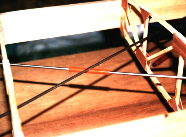
The red rubber tubing that is placed between these wires prevents
chafing of the wires as the engine and other vibrations create oscillations
within these wires. If this chafing was allowed to occur, the wires
would suffer a severe loss of strength and eventual wing failure would
result. The use of rubber has a secondary effect of dampening harmonic
oscillations within the wires which result as a function of the wire material,
length and tension applied to it. This can be compared to a guitar string
which oscillates at a given tone and can be dampened when you place your
finger lightly on the string. Not
shown here, but in a completed wing the crossing point of these wires are
tightly tied using lacing cord or other strong material.
There's one more very important thing
that must be added to this subject. When the holes for the drag and
anti-drag wires are drilled, they are not drilled exactly on the center
line of the spars. They are drilled so that one wire is above the
spar centerline and the other wire is below the centerline. This is to
allow a vertical spacing between the wires where they cross. You
absolutely need this spacing! If the wires touched each other or
are ever so slightly bent around each other, even with the rubber tubing,
they will eventually chafe and lead to a reduction of the strength of the
wing. |